
According to the theory of aerodynamics, as may be readily demonstrated through wind tunnel experiments, the bumblebee is unable to fly. This is because the size, weight and shape of his body in relation to the total wingspread make flying impossible. But the bumblebee, being ignorant of these scientific truths, goes ahead and flies anyway—and makes a little honey every day.
– Igor Sikorsky (adapted from internet)-
In my previous notes on car aerodynamics I briefly introduced the wind tunnel as a testing tool essential to tackle the different problems in the field of car aerodynamics, where most of its effects can, to some extent, be simulated and analyzed. Although the book I mentioned by W-H. Hucho (and almost every book you may read on aerodynamics, related or not to automobiles) devotes some chapters to wind tunnels, let me briefly summarize some relevant aspects:
Types of wind tunnels and main elements.
As the reader can imagine, different typologies of wind tunnels exist to adapt to the measuring and testing requirements. Also budgetary or technology constraints at the time of their design and construction may play an important role. Let´s review the main types and elements.
- Closed vs. open wind tunnels. These are the two main types, the first type called “Göttingen” wind tunnel and the second “Eiffel” wind tunnel. In the first type the air is set in motion by a fan in a closed circuit. In the latter the air is typically “sucked” from the atmosphere, it is general more affordable but with less control of the airflow quality. The closed wind tunnels typically allow a better control of the airflow quality, but they are in turn more complex. This type is however the more extended for full scale automotive testing. For model scale testing or educational purposes Eiffel wind tunnels provide sufficient quality and are often used. Find below NASA pictures to both types:
- Main elements. The main elements of a (closed) wind tunnel can be seen in the previous NASA picture. The fan, responsible to set in motion the air volume (with power values in the range of 1 to 6MW for car testing). The turning vanes, located in the corners in order to properly redirect the airflow while mitigating the buildup of turbulence. The nozzle, with its contracting contour, allows a controlled acceleration of the air producing a less turbulent and more uniform airflow while lowering the power consumption of the fan for a given speed. The test section, where the test object and measurement tools are typically located. This section can in turn be open or closed. Open test sections allow more flexibility to access the car while performing a test program, but are more expensive to build. Its dimension, typically the area of the cross section, is a dimensioning parameter for the wind tunnel design. Finally the collector and diffuser adapt again the airflow to the cross section of the tunnel to meet again the fan and close the circuit.
At this point I recommend to watch this a 22s video at Audi´s Wind Tunnel website showing the airflow in their closed loop tunnel.
In addition, modern car wind tunnels may be equiped with specific systems and elements such as heat exchangers for temperature control, noise and/or turbulence reduction systems, moving ground for roll simulation, etc…
Key parameters.
Having seen the constituting elements of a wind tunnel, let´s take a look at three relevant parameters in their design and operation:
Reynolds number, or the relation between inertial and viscous forces within a fluid, governs the behavior of the airflow around a vehicle, especially of when it comes to turbulent effects. The coefficient puts in relation as well a size and a speed characteristic of the problem to study. Then, for road car aerodynamics, a full scale wind tunnel with airspeeds of 100 to 250km/h give Reynolds numbers that allow a satisfactory simulation of real street situations. For higher speeds (i.e. racing cars) adaptations of test object size or the fluid (speed, pressure, viscosity, etc…) in order to have comparable Reynolds might be necessary.
Contraction ratio, or the relation between the inlet and outlet sections of the nozzle. It was mentioned when describing the wind tunnel elements. This ratio is very much related to the quality of the air, and in fact is more relevant for aircraft wind tunnels in order to achieve a less turbulent airflow (values of this ratio of 10 to 12). However, high ratios allow also a lower power demand to the fan for the same required airspeed. Therefore, also in automotive wind tunnels also high ratios (4 to 6) are taken into account in the design phase (less power demand vs. larger facility). This way, for a ratio of 6, a generated airspeed at the fan of 50km/h is accelerated up to 300km/h at the test section.
Blockage, or the ratio of the cross section of the test object to the cross section of the airstream. This ratio should be kept as low as possible in order to better simulate real open air conditions, where there is no blockage. As the literature indicates, a value of 0,05 should not be exceded, however, for cars with a section of around 2 sqm, this means airstreams from 40 sqm on, and thus test sections greater than 6x6m! (think here about the conversion with the contraction ratio and see the resulting overall dimension of the wind tunnel facilities…). In general, the cross sections of automotive full scale wind tunnels are smaller and calibration measurements are performed to take into account the airstream distortion. (Climatic wind tunnels typically show even higher blockage values of around 0,3 to 0,4)
Power. Finally, the power needed by the fan to set the air volume in motion is rather an economic parameter related to how costly it is to operate a wind tunnel. This power is in general proportional to the characteristic area of the cross section of the tunnel and to the third power of the charateristic speed. It is understandable now why it is preferable to have larger cross sections for a given fan rotating speed, and then accelerate the airspeed by means of a nozzle with high contraction ratio. However, as I noted at the begining and is also common to complex development projects, the resulting design will be influenced by different constraints, technical and economic.
Measuring techniques.
The main purpose of an automotive wind tunnel is to simulate the flow of air around the test object under controlled and repetible conditions, while the car remains tipically in fixed position allowing for different measuring techniques to be employed. These techniques vary depending on the physical magnitude to be measured or the recording support for subsequent analysis. Following the account of aerodynamic problems of my previous notes, find here some of these techniques:
- Forces and moments. In order to measure global forces on the vehicle, mainly the drag and lift in their components (also depending on the relative direction of the car to the airflow) and their resulting moments on the vehicle, typically a complex balance system is built into the wind tunnel test section. Modern facilities integrate the balance with rotating wheels or bands to simulate moving ground, so that the tested car is placed on such integrated module.

Audi Wind Tunnel balance for force and moments measurement (credit to Audi AG)
- Pressure measurements. For a further analysis of the airflow on certain areas, the characterization of the flowfield near the car surface is done by means of pressure probes and transducers. They may be employed in combination with temperature measurements for a better understanding of the aerodynamics in the area. The pressure probes are of special value in car aeroacoustics.
- Flow visualization. In order to have a better qualitative (but also quantitative) understanding of the flowfield around the car, the airflow is made visible by injecting oil smoke by means of probes (see pictures below in the examples). On the surface of the vehicle, pressure sensitive oils and paints help visualize flow patterns as well. In climatic wind tunnels, a flourescent water mixture can be made visible with UV lights. Sometimes, such simple elements as short threads or strings attached to the surface may reveal changes in turbulence behavior or the detachement of the boundary layer (this technique also employed in aircraft flight testing!).
- Anemometry. To know the overall airstream speed or detailed flowfield around the car different anemometry techniques may be used such as simple anemometers, hot wire probes (where the change in the electrical resistance of the hot wire relates to the temperature and speed of the circulating air), ultrasonic anemometry or the more sophisticated laser Doppler anemometry and particle image velocimetry, or PIV (in fact my brother Javier has experience with it from his master thesis!)
- Aeroacoustic. For car aeroacoustics, both interior and exterior, microphones can be employed, in arrays or mounted in probes for the car exterior, or even simulating human ears in dummies seated in the interior! The use of michrophones can be complemented with other techniques for pressure measurement, as was mentioned before.
- Other techniques. Depending on the wind tunnel type, other techniques might be employed, i.e. the mentioned water mixtures in climatic wind tunnels, hot air, helium-filled bubbles, or just photo and video recording for windscreen defrost and deicing analysis.
Examples.
Finally, find below some pictures of notable wind tunnels. First, those owned by car manufacturers seem to be equiped preferably with open test sections, allowing for easy access to the cars and installation of different testing tools without getting into the airstream:

BMW wind tunnel. Note the open test section with moving ground (credit to caricos.com)
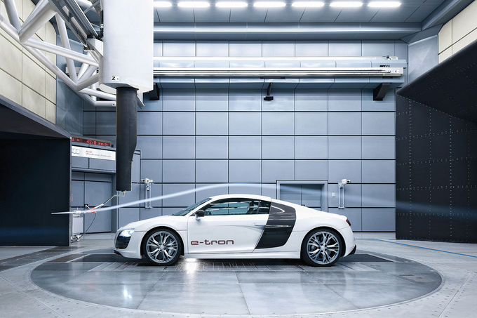
Test section of Audi Wind Tunnel. Note the display for speed and drag results on the left side (from sportauto)

Mercedes Benz wind tunnel open test section, with enough space and elements to perform test programs (credit to Mercedes Benz)
Then, some examples of wind tunnel with closed test sections, here the cases of companies and institutions other that car companies such as RUAG or the dutch-german DNW wind tunnel facility in The Netherlands:
I hope the reader found this post interesting and not too technical follow. As I said at the beginning, the intent of it is to wake interest and direct the reader to the recommended literature. The exciting hours of testing waiting for a low value of drag to appear in a display, or the amazing view of the flow lines under UV lights are definitely worth the effort!

I believe I have seen the quote attributed to Sikorsky.
That is right, I saw this version as incorrectly as anonymous. I will edit it!
Pingback: Memories of my days in a wind tunnel | The Blog by Javier
Pingback: The most and least read in 2014 | jaimeirastorza
Pingback: The most and least read in 2015 … | jaimeirastorza
Pingback: The most and least read in 2017 … | jaimeirastorza